How it works?
A special controller shall be integrated into the battery to ensure monitor application
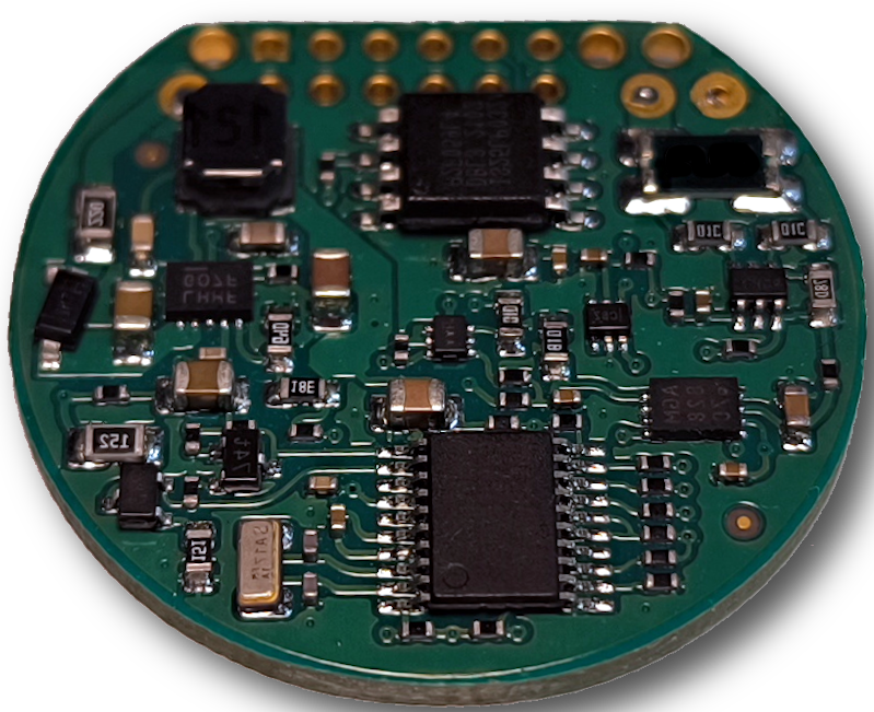
The controller has a simple connection diagram, 3 wires are used:
- Positive wire for power supply
- Incoming negative load lead coming from the battery
- Output negative load lead going to the battery load
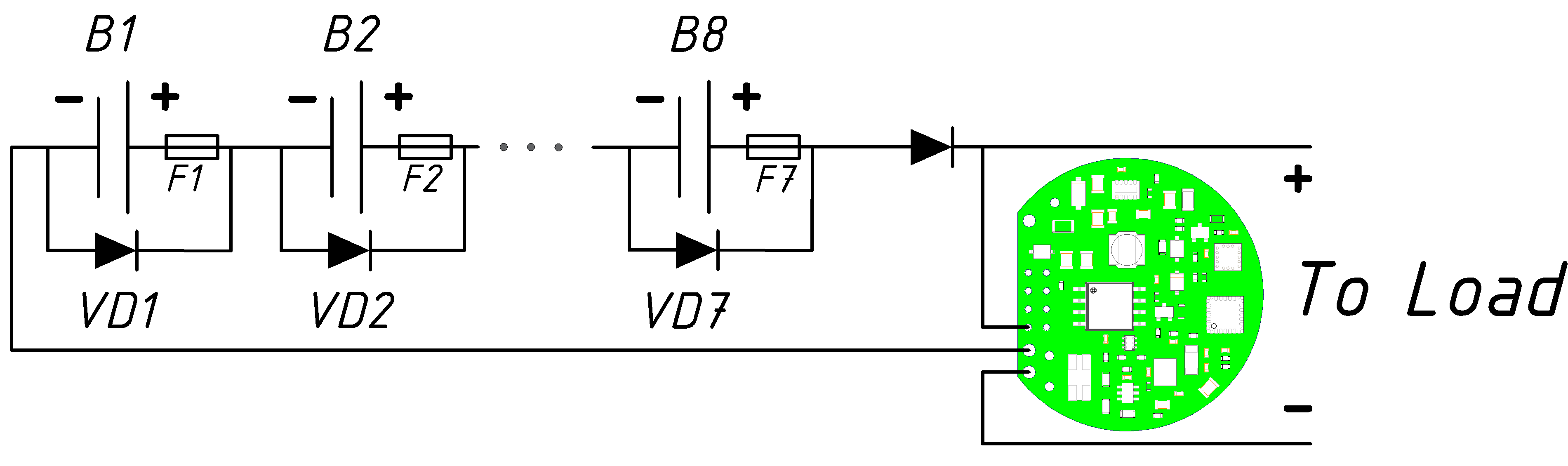
There is no need to use additional wires and no need to use connectors when connecting to the controller reader, data
exchange is performed via a 2-wire circuit using the positive and negative leads from the battery
The current is measured on the negative lead, the positive lead is only required to power the microcontroller
Below are the specifications of the controller
Maximum allowable input voltage | 40 Volts |
|---|---|
Maximum current | 5 Amper |
Current consumption (average value) | 150 microamps |
Minimum operating voltage | 6 Volts |
Maximum battery capacity for evaluation | 100 AH |
Maximum number of events stored in the non-volatile memory | 15625 Records |
Instantaneous current measuring frequency | 0.0625 Sec |
Frequency of measuring average current and voltage values | 1 Sec |
Operating temperature range | -40... +150 °C |
We are willing to add any features you need upon your request!
For additional information please contact to us info@advancedbatterymonitor.com
or send your contact info into box